Pin 2: TD (Output: Transmit Data)
Pin 3: RD (Input: Receive Data)
Pin 4: RTS (Output: Request to Send)
Pin 5: CTS (Input: Clear to Send)
Pin 7: Ground
Pin 20: DTR (Output: Data Terminal Ready)
RTS and DTR are both tied together and set "on"
Data will not be sent unless CTS is "on" (The CTS LED must be on)
The Baud Rate is set with an internal jumper to one of the following settings:
9600 (default)
4800
2400
1200
600
300
The communications parameters are hard wired for 1 start bit, 8 data bits, 1 stop bit, and no parity.
The data sample rate / periodicity for the Data Inputs is set with an internal jumper to one of the following settings:
18.8 Hz
9.4 Hz
4.7 Hz
2.3 Hz
1.2 Hz (default)
1.7 seconds
3.4 seconds
14 seconds
Data is sampled at the instance when the Clock LED on the indicator panel turns on.
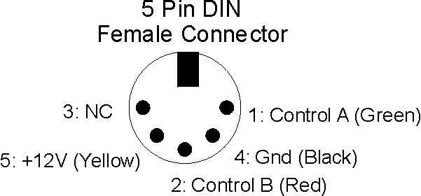
Pin 1: Signal (or Control) A [Green]
Pin 2: Signal (or Control) B [Red]
Pin 3: Not Used (Reserved for Signal or Control C)
Pin 4: Ground [Black]
Pin 5: 12V [Yellow]
The order of the pins are clockwise (for the female connector) from the "key": 1,4,2,5,3

There are 8 five-pin DIN connectors for the input ports. Pin one of each of the connectors is connected to the appropriate input on the serial interface. The Odd bits (D1, D3, D5, D7) are also connected to Pin 2 of the next lower connector (D0, D2, D4, D6 respectfully). In this way, one connector can provide input for 2 bits and only 4 connectors are needed for all 8 bits.
As with the input ports, there are 8 five-pin DIN connectors for the output ports. Pin one of each of the connectors is connected to the appropriate output on the serial interface. The Odd bits (D1, D3, D5, D7) are also connected to Pin 2 of the next lower connector (D0, D2, D4, D6 respectfully). In this way, one connector can provide input for 2 bits and only 4 connectors are needed for all 8 bits.
Each of the output port bits can sink up to 300 ma of current when a "1" is written. In the high-impedance state (when a "0" is written), the output port can withstand up to 30 Volts DC. For more information see the data sheet for the 75451 Dual Peripheral Drivers.